how-to
How to Print Complex Geometries: A Step-by-Step Guide

Last Updated: October 10, 2026
Understanding Complex Geometry in 3D Printing
Complex geometry in 3D printing refers to designs with intricate features, sharp angles, thin walls, overhangs, or internal cavities that challenge standard printing methods, making it essential to understand how to print complex geometries successfully.
When you design something with complex geometry, you're asking your printer to do more than deposit material in simple layers. You're asking it to bridge gaps, support unsupported features, and maintain detail in tight spaces.
The difference between a failed print and a successful one often comes down to how well the designer understands their printer's limits before hitting send.
Complex geometries include:
Internal channels or lattice structures
Thin walls or delicate features
Overhangs exceeding 45 degrees
Undercuts or enclosed cavities
Curved surfaces requiring smooth transitions
Small details under 1mm
The challenge isn't that your printer can't handle complexity. It's that complexity requires intentional design choices. Skip those choices, and your print fails halfway through.
Preparing Your CAD Model for Complex Prints
Getting your CAD model ready is where most projects succeed or fail. A good design file saves time, material, and frustration. A poor one wastes both.
Start by exporting your model in a format your slicer software accepts. STL and OBJ files are standard. Check that your model is watertight, meaning every surface is sealed with no gaps or holes. A non-watertight model confuses your printer's software and produces unprintable results.
Design-for-printing checks and file validation
Before sending your model to print, run these checks:
Mesh integrity: Use your slicer's analysis tool to scan for non-manifold geometry, reversed normals, or holes. Most slicers flag these automatically. Fix them before proceeding.
Wall thickness: Measure your thinnest walls. For FDM printing, walls should be at least 1.2mm thick. For resin printing, 0.8mm is acceptable. Thinner walls break during printing or post-processing.
Hole size: Any hole smaller than 2mm in diameter risks clogging with support material or uncured resin. Consider whether that hole is essential or if you can enlarge it slightly.
Feature size: Details smaller than 0.5mm often fail to print. If your design relies on tiny features, test with a small prototype first.
Run a test slice in your slicer before committing to a full print. The preview shows you exactly what will print and where problems exist.
Optimizing models for printability
Optimization means making your complex geometry actually printable without sacrificing your design intent.
Simplify where possible: Look for areas where you can reduce complexity without affecting function.
Orient internal features: If your model has internal channels, orient them so they're accessible for cleaning. Horizontal channels are easier to clear than vertical ones.
Strengthen weak points: Where your design has thin sections connecting larger volumes, add subtle reinforcement. A 0.5mm fillet at a joint prevents cracking during removal.
Check draft angles: Surfaces that slope away from the build direction (positive draft) print cleaner than vertical walls. A 2-5 degree angle improves surface quality.
Separate if needed: If your complex geometry includes multiple parts that could be printed separately and assembled, consider splitting the model.
3D Print Orientation: Positioning Your Model for Success
How you position your model on the build plate directly affects print success. Orientation controls where supports go, how long printing takes, and final surface quality.
Complex design from start to finish - 3D design for 3D printing pt11
Teaching Tech
The best orientation balances three competing goals: minimizing supports, reducing print time, and maximizing surface quality in visible areas.
Handling overhangs and unsupported features
An overhang is any feature that extends beyond the layer below it without support. For FDM printing, overhangs steeper than 45 degrees need support material.
Rotate to reduce overhangs: Tilt your model so overhangs become less steep or disappear entirely. A 15-degree rotation often eliminates the need for supports on moderate features.
Identify critical overhangs: Not all overhangs are equal. An overhang on a hidden surface matters less than one on a visible face.
Accept some supports: Sometimes you can't eliminate overhangs without compromising your design. That's when you accept supports and plan to remove them carefully.
Test orientation: Before committing to a full print, slice your model in different orientations. Compare support material volume and print time. The orientation that uses least support often prints fastest and cleanest.
Support Structures for 3D Printing Complex Geometries
Supports are temporary structures that hold up overhangs and floating features when you print complex geometries during the printing process. They're essential for complex geometry but they consume material and require careful removal.
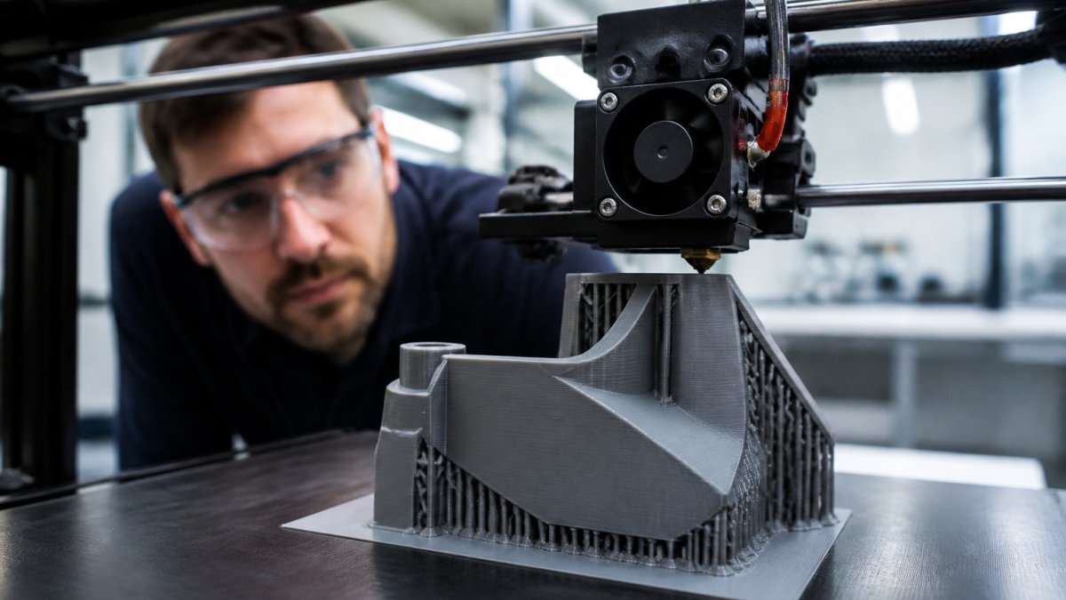
Using supports and minimizing support material
Your slicer generates supports automatically based on your settings. But you can guide that process to minimize waste.
Set support angle threshold: Most slicers let you specify the steepness at which supports activate. For FDM, 45 degrees is standard.
Use tree supports if available: Tree-style supports branch like a tree rather than forming solid columns.
Place supports strategically: Some slicers let you manually add or remove supports. Remove supports from visible surfaces and keep them on hidden areas.
Adjust support density: Denser supports hold features more reliably but waste material and take longer to remove. Start with medium density and increase only where needed.
Orient for support efficiency: Sometimes rotating your model slightly reduces support volume dramatically. Test a few orientations before settling on one.
Support removal and assembly tolerances
Removing supports is where many prints fail. Poor removal damages the part or leaves rough surfaces.
Plan removal strategy: Before printing, identify how you'll access and remove supports. Supports on the top surface are easier to remove than those buried inside cavities.
Use break-away supports: Many slicers offer supports designed to snap off cleanly. These save time compared to supports that require cutting or dissolving.
Post-process carefully: After removing supports, sand rough areas lightly. For resin prints, wash thoroughly to remove uncured resin before sanding.
Account for assembly tolerances: If your complex geometry includes parts that fit together, add 0.2-0.3mm clearance between mating surfaces.
Test fit before final assembly: Print a test version with assembly features. Check that parts fit without forcing. Adjust tolerances if needed and reprint.
FDM vs Resin 3D Printing for Complex Designs
Choosing between FDM and resin printing shapes everything that follows. Each technology handles complex geometry differently.
FDM (Fused Deposition Modelling) builds parts by extruding plastic filament layer by layer. It's reliable, affordable, and handles large parts well. But FDM struggles with fine details and overhangs.
Resin printing uses UV light to cure liquid resin into solid parts. It captures intricate detail and produces smooth surfaces. But resin prints are smaller, more fragile, and require careful post-processing.
For complex geometry with fine details, resin usually wins. For large, functional parts with moderate complexity, FDM is better.
Consider your tolerances, surface finish requirements, and part size. A small intricate component suits resin. A large bracket with some complexity suits FDM.
Slicer Settings and Troubleshooting for Intricate Prints
Your slicer software translates your CAD model into instructions your printer understands. The settings you choose directly affect whether your complex geometry prints successfully.
Layer height, print speed, and geometric features
Layer height controls how thick each printed layer is. Smaller layers capture finer detail but take longer to print. For complex geometry, use 0.1mm layers instead of the standard 0.2mm.
Print speed affects how fast your printer moves. Slower speeds give the material time to bond properly, especially important for intricate features. Reduce speed by 20-30% for complex prints compared to simple ones.
Nozzle temperature matters more with complex geometry. Higher temperatures help material flow smoothly around tight corners. Lower temperatures risk incomplete bonding. Test your material's recommended range and stay toward the upper end for complex prints.
Infill percentage affects interior density. For parts with complex internal geometry, 15-20% infill is usually enough. Higher infill adds weight and printing time without improving strength for most designs.
Common failures and how to prevent them
Stringing: Thin plastic threads between separate features. Reduce nozzle temperature by 5°C or increase retraction distance.
Layer separation: Layers don't bond properly, causing parts to delaminate. Increase nozzle temperature or reduce print speed.
Incomplete features: Thin walls or small details fail to extrude. Reduce layer height or slow print speed.
Support marks: Rough surfaces where supports attached. Use finer support tips or angle supports differently.
Warping: Edges curl upward, especially on larger prints. Increase bed temperature or use a heated chamber if available.
Test one setting change at a time. Print a small test part before committing to a full print. This saves material and identifies problems early.
3D Printing Without Supports: When and How
Some designs can print without supports if you orient them carefully. This saves material and post-processing time.
Designs that work without supports typically have:
No overhangs steeper than 45 degrees
No enclosed cavities
No floating features
Gradual slopes rather than sharp angles
To print without supports, orient your model so all features slope gently downward. Rotate until your slicer shows zero support volume needed.
Not every design can print support-free. Know your limits. If supports save material or improve quality, use them. The goal is a successful print, not avoiding supports at all costs.
Post-Processing and Assembly for Complex Parts
Printing ends when the part leaves the printer. Post-processing transforms a raw print into a finished part.
For FDM prints, remove supports and sand rough areas. Start with coarse sandpaper and progress to fine grit. A 400-grit finish usually looks professional.
For resin prints, wash thoroughly in isopropyl alcohol to remove uncured resin. Cure in UV light if recommended. Sand lightly if needed.
If your complex geometry includes multiple parts, test fit before final assembly. Use cyanoacrylate glue for plastic parts or epoxy for resin. Clamp joints while adhesive cures.
Paint or coat finished parts if desired. Primer helps paint adhere better to printed surfaces.
Step | Time | Key Point |
|---|---|---|
CAD preparation | 30-60 min | Validate mesh, check wall thickness |
Orientation testing | 15-30 min | Slice multiple orientations, compare |
Slicing and settings | 20-40 min | Adjust layer height, speed, supports |
Printing | Varies | Monitor first layer and early print |
Support removal | 15-45 min | Remove carefully, plan access points |
Post-processing | 30-90 min | Sand, wash, cure, paint as needed |
Printing complex geometries demands planning, but it's entirely achievable with the right approach.
At Kreative3D, we handle complex geometry prints regularly.
Frequently Asked Questions
How do you 3D print complex shapes without supports?
The key is strategic model orientation and design modification. Rotate your model so overhangs face downward or are minimized. Split complex geometries into separate parts that assemble after printing, eliminating the need for internal supports. Use design software to add small fillets or chamfers that reduce sharp angles. For FDM printing, orient the model so layers build vertically where possible. Resin printing handles steeper angles better, so choose resin if your geometry has extensive overhangs. Validate your design in slicing software before committing to print.
What's the difference between FDM and resin 3D printing for complex geometries?
FDM extrudes molten plastic layer-by-layer and handles structural complexity well but struggles with fine details and overhangs. Resin printing uses UV light to cure liquid resin and produces superior detail, thin features, and complex curves with minimal support material. FDM is faster and cheaper for large parts; resin excels at precision and intricate geometry. For highly detailed models with complex internal structures, resin wins. For functional prototypes with moderate complexity, FDM is reliable and cost-effective. Your choice depends on whether you prioritize detail or speed and cost.
How should you orient a complex 3D model for printing?
Orientation directly affects print success, support material, and surface finish. Position the model so the fewest overhangs face upward. Rotate it to align thin features and fine details vertically when possible, as horizontal layers show better definition. Avoid placing delicate geometry directly on the build plate; use a slight angle to improve adhesion and reduce stress. For FDM, orient load-bearing features along the layer direction for strength. Use your slicer's preview to check support placement and adjust orientation to minimise material waste. Test orientation on a smaller scale model first if geometry is very intricate.
What are support structures and when do you need them?
Support structures are temporary scaffolding that holds overhanging geometry in place during printing. You need them when your model has features that extend more than 45 degrees from vertical (for FDM) or when resin sections would collapse without anchoring. Supports prevent drooping, warping, and print failure. Modern slicers generate supports automatically, but you can refine them to reduce material waste and post-processing time. Remove supports after printing by cutting, snapping, or dissolving them depending on material and design. Minimise supports by rotating your model and splitting complex parts into assemblies.